
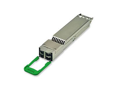
Upgrading a data center network to 800G does not always mean replacing the entire fiber infrastructure. Many facilities already have OS2 single-mode fiber, LC patch panels, and structured cabling installed for 100G, 400G, or other high-speed links. Some of this infrastructure may remain suitable for 800G FR4, helping control upgrade costs and reduce installation work. However, connector compatibility alone is not enough. The complete optical channel must meet the requirements of the target transceivers.
Start with the Existing OS2 Fiber
800G FR4 is designed for high-speed transmission over single-mode fiber, typically supporting distances up to 2 km under specified conditions. If the existing network uses OS2 cabling, the fiber type may already be suitable.
Before reusing it, verify the actual route between the two endpoints. Check the installed fiber type, total length, routing records, and any undocumented extensions or repairs. A link that appears short on a floor plan may include additional cable runs through intermediate distribution areas.
Fiber condition also matters. Contaminated end faces, damaged jumpers, excessive bends, and poorly maintained connections can degrade optical performance. Inspecting and cleaning connectors before testing helps establish whether the existing channel is suitable for reuse.
Check LC Patch Panels and Jumper Compatibility
Many 800G OSFP FR4 implementations use duplex LC optical interfaces, but the exact configuration depends on the transceiver design. Confirm the connector type and interface arrangement in the product datasheet before ordering patch cords or planning a migration.
Next, inspect the patch panels, adapters, and jumpers along the route. Existing LC infrastructure may be reusable, but every connection adds potential insertion loss. Older connectors, mixed-quality patch cords, and unnecessary cross-connects can make the overall channel harder to qualify.
Polarity and end-to-end connectivity should also be verified. The transmit path at one end must connect correctly to the receive path at the other. Clear labeling and updated cabling records reduce the risk of installation errors, especially when multiple links are upgraded in parallel.
Calculate the Complete Link Loss
A fiber link can use the correct cable type and connector yet still fail to meet the optical requirements of an 800G application. The key is to evaluate the entire channel, including fiber attenuation, mated connector pairs, and any splices.
Compare the measured insertion loss with the limits specified for the selected transceiver and application. Do not assume that a link qualified for 400G will automatically satisfy every 800G FR4 implementation. The target module’s optical specifications and the complete channel design determine whether reuse is appropriate.
For critical links, use calibrated test equipment and retain baseline measurements. These records help distinguish existing infrastructure problems from issues introduced during the upgrade.
Reuse What Works, Replace What Does Not
Replacing every cable by default can increase material costs, labor, and deployment time. Reusing a qualified OS2 channel can preserve existing investments while limiting unnecessary disruption. However, retaining unsuitable jumpers or poorly documented connections may create troubleshooting costs later.
A practical approach is to inspect the channel, verify connector compatibility, measure insertion loss, and document the results before migration. Replace only the components that fail inspection or testing, and confirm that the final configuration meets the transceiver manufacturer’s requirements.
Make Infrastructure Readiness Part of the Upgrade Plan
Before deploying 800G FR4, review the OS2 fiber route, LC interfaces, patch cords, connection count, and measured channel loss. Check the transceiver datasheet for supported distance, optical limits, and interface details rather than relying on connector appearance alone.
A well-qualified existing fiber plant can make an 800G upgrade more cost-effective. The goal is not simply to reuse as much cabling as possible, but to preserve the infrastructure that meets the new requirements and replace the parts that do not.